
RUIDE / RD-LXKT-80
Ruide RD-LXKT-80 — Centrifugal Industrial Air Conditioner
30 kW rated cooling with circulating-water heat rejection, selected around the real load and air-distribution needs
Understand the equipment, ratings and design requirements before selecting it for your industrial workspace.
What is the RD-LXKT-80?
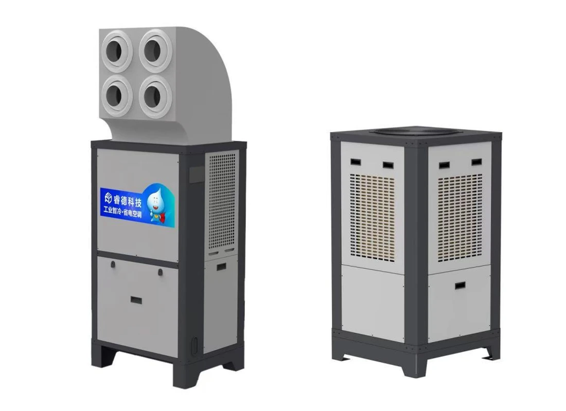
The Ruide RD-LXKT-80 is a centrifugal-type industrial air conditioner. The supplier lists an 8HP model designation and 30 kW rated cooling capacity. It is a candidate for applications that distribute cooled air to defined work areas, subject to load and airflow design.[1]
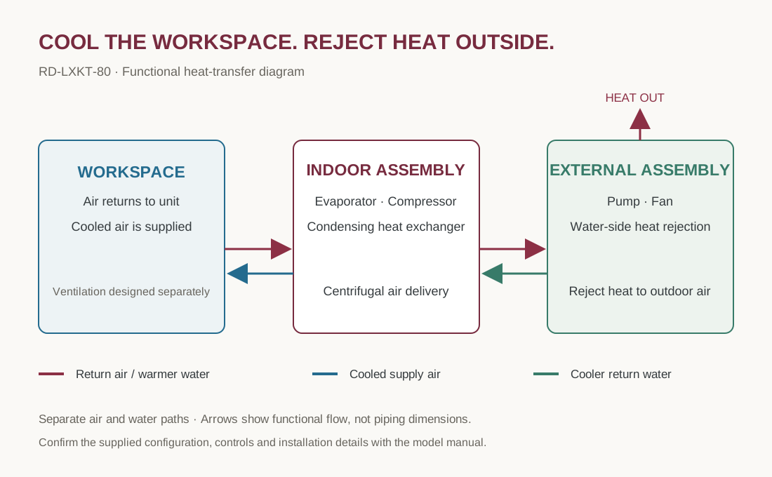
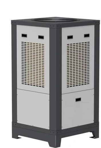
The manufacturer describes an indoor assembly containing a compressor, evaporator and condensing heat exchanger. Circulating water transfers heat to an external assembly equipped with a pump and fan.[2]
Separate cooling and heat rejection
The indoor refrigeration system removes heat from the conditioned air. The water circuit carries condensing-side heat to the external assembly for rejection. Locate the heat-rejection equipment so its discharge does not return to the cooled work area.[2]
This arrangement should not be confused with a direct evaporative air cooler that passes supply air over a wet medium. The available documents do not specify dehumidification performance; request coil data for humidity-critical applications.
Practical strengths
- Centrifugal airflow: a candidate for distribution systems with resistance. Obtain the model’s fan curve and external static pressure before confirming delivered airflow.[4]
- 30 kW rated cooling: a starting point for industrial-zone load assessment, subject to rating conditions.[1]
- Separate heat rejection: cooling and heat disposal can be located separately, with a properly designed water circuit.[2]
- Defined duct connection: the listed 400 × 250 mm flange supports interface planning; it does not determine the size of every duct section.[1]
Manufacturer specifications
Transcribed from RUIDE Energy Saving Industrial ACs Quotation, page 1, RD-LXKT-80 entry. Prices are excluded. A dash means no value is shown for that assembly, not zero.[1]
| Parameter | Indoor assembly | External assembly |
|---|---|---|
| Model | RD-LXKT-80 (8HP designation) | — |
| Rated cooling capacity | 30 kW | — |
| Rated power | 6.5 kW | Not stated |
| Power supply | 380 V / 3 Ph / 50 Hz | 380 V / 3 Ph / 50 Hz |
| Maximum airflow | 7,000 m³/h | — |
| Air supply distance | 30 m | — |
| Rated current | 12 A | 1.5 A |
| Energy efficiency ratio | 4.8 (as listed) | — |
| Water supply connection | DN 15 | DN 15 |
| Water inlet & outlet | DN 25 | DN 25 |
| Water storage | — | 55 L |
| Pump head | — | 18 m |
| Pump suction stroke | — | 9 m |
| Duct flange | 400 × 250 mm | — |
| Number of air outlets | 10 (as listed) | — |
| Weight | 180 kg | 120 kg |
| Applicable area | 200–300 m² | — |
| Dimensions | 602 × 802 × 1300 mm | 770 × 770 × 1461 mm |
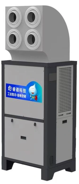
The document does not define the dimension-axis order. The listed 10 air outlets differs from the four circular openings visible on the pictured discharge head; confirm the supplied head and the intended distribution configuration.
Assess energy performance at system level
The manufacturer’s design uses circulating water to assist condensing-side heat rejection.[2]
The supplier table lists an energy efficiency ratio of 4.8 and rated power of 6.5 kW without ratio units, test conditions or a clear energy boundary. Dividing 30 by 6.5 gives approximately 4.62, so clarification is required before using these figures for an efficiency comparison.[1]
Evaluate the indoor assembly, external fan and pump, water use, maintenance, actual load and operating hours together. Establish comparable loads and weather conditions for before-and-after measurements. A savings percentage or payback period cannot be established from these ratings alone.
Suitable application scenarios
The following are engineering selection suggestions, subject to project-specific assessment.
| Situation | Potential approach | Checks needed |
|---|---|---|
| Assembly or packing zone | Deliver cooled air to defined working areas | People, machine heat, return path and duct resistance |
| Indoor production area | Assess zoned environmental control | Dust, vapours, process requirements and humidity |
| Local hot spots in a factory hall | Consider zone cooling | Cross-zone air exchange, doors and roof radiation |
| Space for external heat rejection | Separate heat disposal from occupied areas | Water supply, discharge, airflow and service access |
Humidity-critical work, cleanrooms, flammable atmospheres and corrosive environments require additional evidence and project requirements. The available model documents do not establish suitability for these special applications. Recirculating cooling also does not replace outdoor-air ventilation or local contaminant extraction.
Design checks before installation
- Cooling load: assess envelope, sunlight, people, machines, outdoor air, leakage and moisture loads.[3]
- Air distribution: obtain fan curves and external static pressure; calculate duct, bend, terminal and filter resistance. Arrange a return path that avoids short-circuiting.[4]
- Water system: confirm flow, pipe and elevation limits, make-up water, water quality and cleaning. The stated pump head and suction figures are not stand-alone installation distances.
- Electrical supply: use the delivered nameplate and manual for cable, protection and earthing design, rather than listed running current alone.
- Service access: plan drainage, vibration and noise management, access and structural support.
Operation and care
Commission electrical connections, water flow, valves, airflow and heat rejection according to the model manual. Set an appropriate operating target and keep inlet and discharge paths clear. Monitor temperature and humidity where people work, rather than only at the outlet.
- Check water level, leaks and pump operation according to the manufacturer’s procedure.
- Clean airflow paths, coils and the water system at intervals suited to the manual and actual conditions.
- Watch for scale, fouling and declining heat rejection.
- Investigate abnormal noise, vibration, temperature or current through qualified personnel.
- Refrigerant and electrical servicing require competent technicians; the model manual governs start-up and maintenance procedures.
Questions before selection
Can it run on a 220 V domestic supply?
The table specifies 380 V, three-phase, 50 Hz for both assemblies. Confirm the site supply and delivered nameplate.
Does 30 m mean a guaranteed duct length?
No. It is the listed air-delivery distance. Duct length and resistance require the fan curve and configuration-specific assessment.
Does water use imply humidified supply air?
The manufacturer describes water on the heat-rejection side. This does not establish direct humidification of supply air; confirm construction and coil performance for humidity-critical work.
What information is still required?
Refrigerant type and charge, noise, external static pressure, water flow and consumption, operating range, controls, manuals, test conditions and EER boundary, dimensional drawings and any project-specific certification.
Sources
- RUIDE Energy Saving Industrial ACs Quotation — RD-LXKT-80, page 1; supplier specification table, undated, with no test standard stated.
- RUIDE — RD-LXKT-80 manufacturer exhibitor description, VietnamPlas 2026 ↗
- ASHRAE Handbook (2025) — Nonresidential Cooling and Heating Load Calculations ↗
- AMCA — Straightening Out Fan Curves ↗
DISCUSS YOUR PROJECT
Is the RD-LXKT-80 right for your workspace?
Share a floor plan, site photos, cooling targets, machinery and electrical supply information. Siamphat can assess the load, airflow and supporting systems to inform equipment selection and installation planning.