
07 / Fans & air distribution
Fans, ducts & air distribution
Useful airflow comes from a fan and a distribution system that fit.
A catalogue maximum may describe a low-resistance condition. Adding ducts, filters and terminals changes the airflow. Selection must pair the required flow with the pressure the actual system needs.
Supply, exhaust and circulation duties serve different purposes. Duct layout and terminal placement deserve the same attention as the fan itself.
Content reviewed 6 October 2026
Discuss the application →
Find the restriction before increasing fan size
Low delivery can result from loaded filters, closed dampers, undersized ducts, leakage or poor inlet/outlet conditions. High fan discharge flow still does not prove delivery to all zones.
Check model, speed, filter state, damper positions and branch flows before modification. More speed can add noise and input while leaving the distribution problem intact.
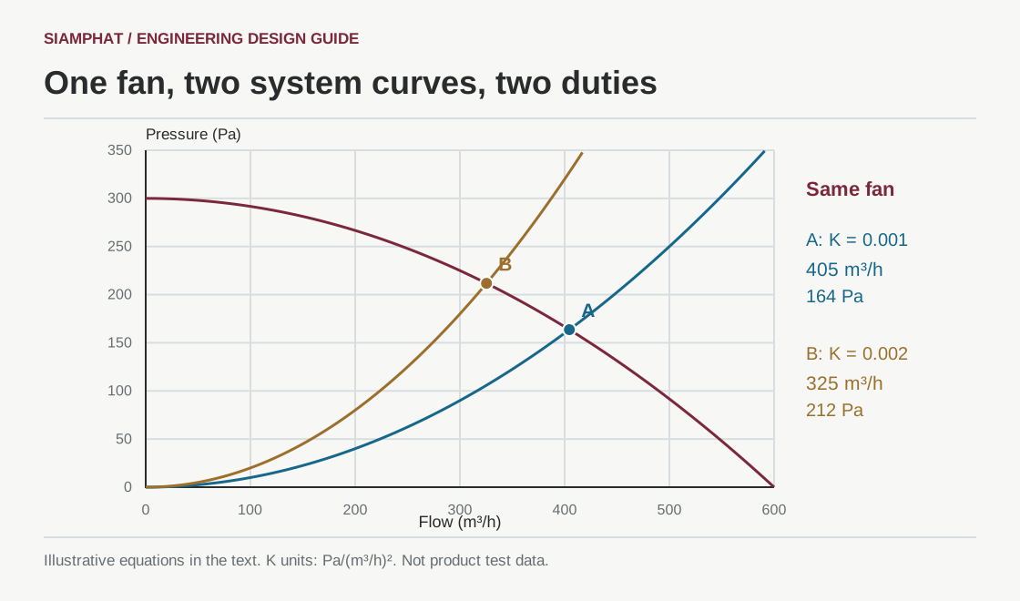
The duty point joins fan and system curves
A fan curve relates flow and pressure at a specified speed and test condition. A system curve describes the pressure required as flow changes. Their intersection is the operating point.[1]
For suitable fixed-path flow conditions, many resistance components can be approximated by Δp = KQ². Room-pressure offsets, moving dampers or different flow regimes need appropriate treatment. Use matching static/total-pressure and density bases.
Choose type from duty, not appearance
| Type/approach | Context | Check |
|---|---|---|
| General axial fan | High flow with low resistance | Model curve, sound and installation |
| Centrifugal fan | Duct/filter resistance appropriate to the model | Impeller, input, duty point and stable range |
| Specialised axial or other designs | Engineered pressure/performance duties | Do not equate with common low-pressure axial products |
| Compatible EC/BLDC or variable-speed drive | Changing flow or loads | Motor/drive compatibility and sequences; not a substitute for sizing |
Impeller and motor arrangements vary. Pressure claims need model curves; no fan category wins every application.
Specify the complete duty
- Required flow and path pressure: intake, filters, ducts, terminals and relevant room pressure.
- Consistent pressure definition and air-density basis.
- Stable range, efficiency, shaft/motor input and drive capability across the intended range.
- Sound data with matching methods and distances.
- Environment, material, mounting and access to the fan and motor.
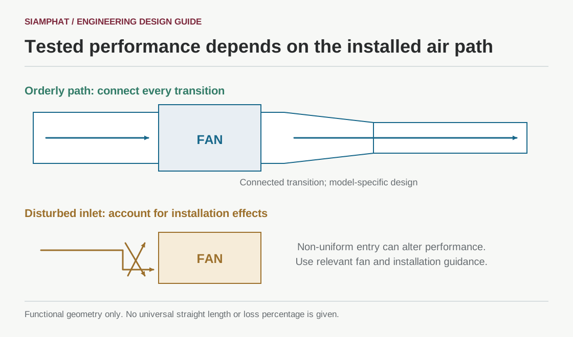
Installation can change tested performance
Swirl or non-uniform inlet flow and unsuitable outlet transitions/bends can create system effect. Allow the layout to support the required air development and account for installed losses.[2]
There is no universal straight-duct distance in this illustration. Use guidance relevant to the fan and manufacturer. A rectangular fan discharge feeding round duct needs a real, properly designed connected transition.
Application: filtered supply into a sealed room
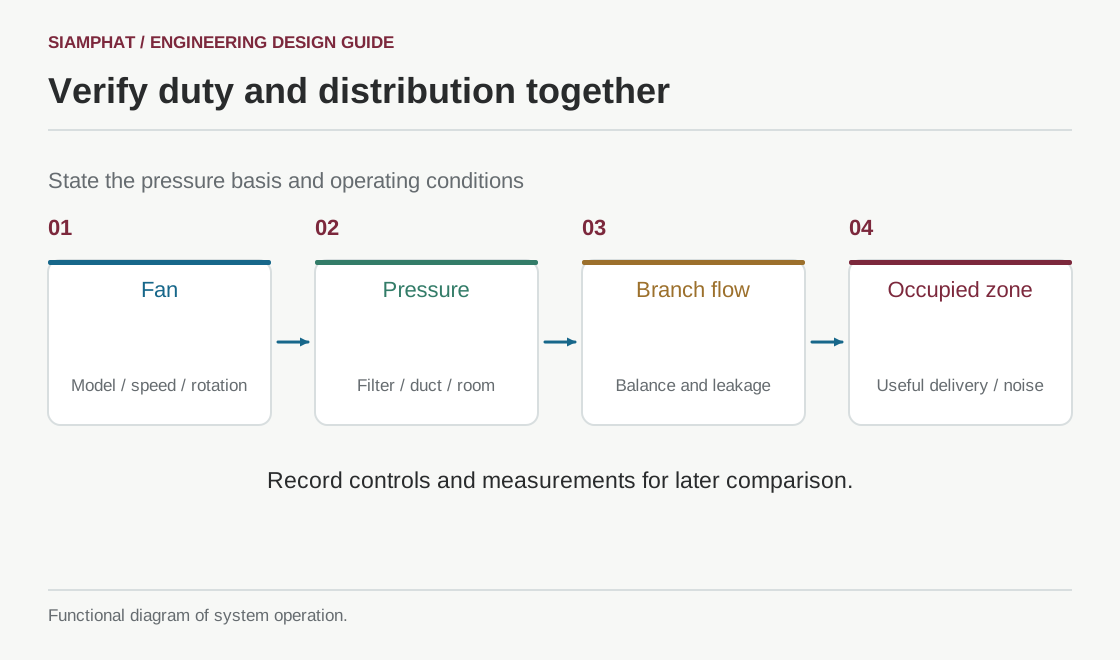
Verify from the machine to the occupied zone
- Model, speed, rotation, installation and filter/damper states.
- Flow and pressure using suitable methods and locations, with pressure definition recorded.
- Branch balancing and relevant occupied-zone velocities.
- Speed commands, alarms and electrical input within the agreed scope.
Record a baseline to distinguish later loading, layout and demand changes. Rebalance when terminals or use change. A single sensor point needs justification before it represents the entire system.
Siamphat selects the fan with the ducts and terminals
We connect air duty to path resistance, controls, sound, installation and verification. Equipment is assessed as part of the system it must serve.
Bring airflow plans, fan/filter details, weak-delivery locations and spatial constraints. Where drawings are absent, the operating brief guides what needs surveying.
Questions about fans and ducts
Can maximum catalogue flow select the fan?
Select at the actual required pressure; low-resistance maximum delivery can be very different.
Does filter loading always reduce flow?
Fixed-speed operation typically changes duty; flow-controlled systems may increase speed until a limit. Check the actual sequence.
How much energy does reducing speed save?
Similarity laws have conditions. System duty, efficiency and load determine actual input; do not infer a project percentage from speed alone.
How much straight duct is required?
Use fan-specific inlet/outlet and manufacturer guidance, not a universal distance.
References and scope
- AMCA — Straightening Out Fan Curves ↗
- AMCA — Mitigating System Effect to Optimize Fan Performance and Efficiency ↗
- ASHRAE Handbook — Air Handling and Distribution (2020) ↗
Sources support principles; they are not product certificates or a claim of project compliance. Actual design requires the applicable editions, requirements, model data and installation conditions. Residential or general sensor guidance does not substitute for special-purpose building criteria.
Connect the complete system
DISCUSS YOUR PROJECT
Strong fan, but insufficient useful airflow?
Discuss the fan, ducts, filters and terminals together with us to assess the operating point and airflow path.
Start with a plan, site photographs, existing equipment and the times when the problem occurs.