
ENGINEERING / FAN PERFORMANCE
Centrifugal vs Axial Fans: Choose the Actual Operating Point
A high free-air rating does not guarantee adequate airflow through a filter into a sealed room. Fan curves, system resistance and air balance explain which fan fits a dust-protection positive-pressure room.
Published 5 October 2026
High airflow and resistance capability are different qualities
A fan that moves more air into an open space may deliver less when connected to a filter and a sealed room. Ask for airflow at the required pressure, not the largest airflow number on the label. For a dust-protection room, the result must be filtered outdoor supply air and a suitable pressure difference relative to the reference area.
Two airflow families, with Thai names
Axial Fan is พัดลมแบบไหลตามแนวแกน: the principal flow passes along the shaft axis. Centrifugal Fan is พัดลมแบบแรงเหวี่ยงหนีศูนย์กลาง: air enters near the wheel centre and leaves towards its outer radius. A housing then collects or redirects it. Thai engineering terminology
An inline housing does not identify the impeller family: a centrifugal wheel can be installed in a housing with aligned external inlet and outlet connections. Check the internal wheel type and manufacturer documentation.
Ordinary axial ventilators suit high flow and low resistance
Here, ordinary axial fans means propeller-style and basic ventilation products designed for low-resistance applications, such as short wall openings. Their free-air rating must not be treated as installed flow through a restrictive filter or complicated ductwork.
Specialised axial designs, including vaneaxial fans, use suitable blade geometry and guide vanes for greater pressure capability. They are a different selection category from basic household ventilators. Do not assume that a specialised axial solution is cheaper than a comparable centrifugal solution: obtain quotes at equal duty, noise and control requirements. This article does not claim a Thai price or market-share survey. Greenheck vaneaxial application guide
The intersection determines actual airflow
A fan curve relates flow Q to fan pressure rise at specified speed, size and air density. A system curve describes the pressure required to move each flow through the installation. Their stable intersection is the operating point. AMCA fan-curve principles
Maximum free-air flow and maximum pressure near zero flow are separate points. They are not a simultaneous duty rating. Keep static and total pressure definitions consistent; account for velocity pressure and test boundaries when converting between them.
A higher free-air rating can lose at higher resistance
The first chart is a calculated teaching model, not a product rating or a universal curve shape. Fan A has a 600 m³/h free-air intercept; C has 500 m³/h. At fixed speed and lower resistance L, A delivers about 526 m³/h and C about 483 m³/h. With higher resistance H, A delivers about 256 m³/h and C about 350 m³/h.
The lesson is not that every centrifugal fan beats every axial fan. It is that comparing free-air ratings alone can reverse the practical conclusion once system resistance is considered.
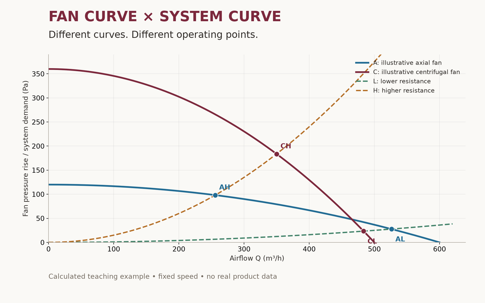
| Point | Q (m³/h) | ΔP (Pa) |
|---|---|---|
| AL | 526 | 27.7 |
| AH | 256 | 98.2 |
| CL | 483 | 23.4 |
| CH | 350 | 183.7 |
Dust protection: seal, pressurise and filter
Seal uncontrolled entry paths; supply filtered outdoor air so leakage tends outward; and filter incoming air plus recirculated room air as appropriate. These functions work together. “Push dust out” is a mnemonic for discouraging inward contaminated airflow, not a promise that pressure removes every particle. A recirculating purifier alone does not add outdoor air to pressurise a room. EPA on pressurisation with filtration
Open doors, wind, exhaust fans and indoor sources still affect the outcome. Verify room differential pressure and actual PM2.5 conditions. Positive pressure is not a guarantee of zero dust. EPA indoor particulate matter
A tighter room resists flow, but may need less leakage makeup
At the same supply flow, fewer leakage paths require greater room pressure to pass that air outward. Conversely, a better seal can reduce the flow needed to maintain the same room pressure. Neither relationship removes the need for adequate occupant ventilation.
At steady state, total inflow equals total outflow. If unwanted inflow is absent, a simplified balance is Q_supply = Q_exhaust + Q_leak,out. Include bathrooms, kitchens and other exhaust according to actual use. Provide suitable relief or pressure control rather than treating an occupied room as a completely blocked container. A dust-protection room has a different purpose from an infection-isolation or smoke-control system.
Filter loss is not room pressure
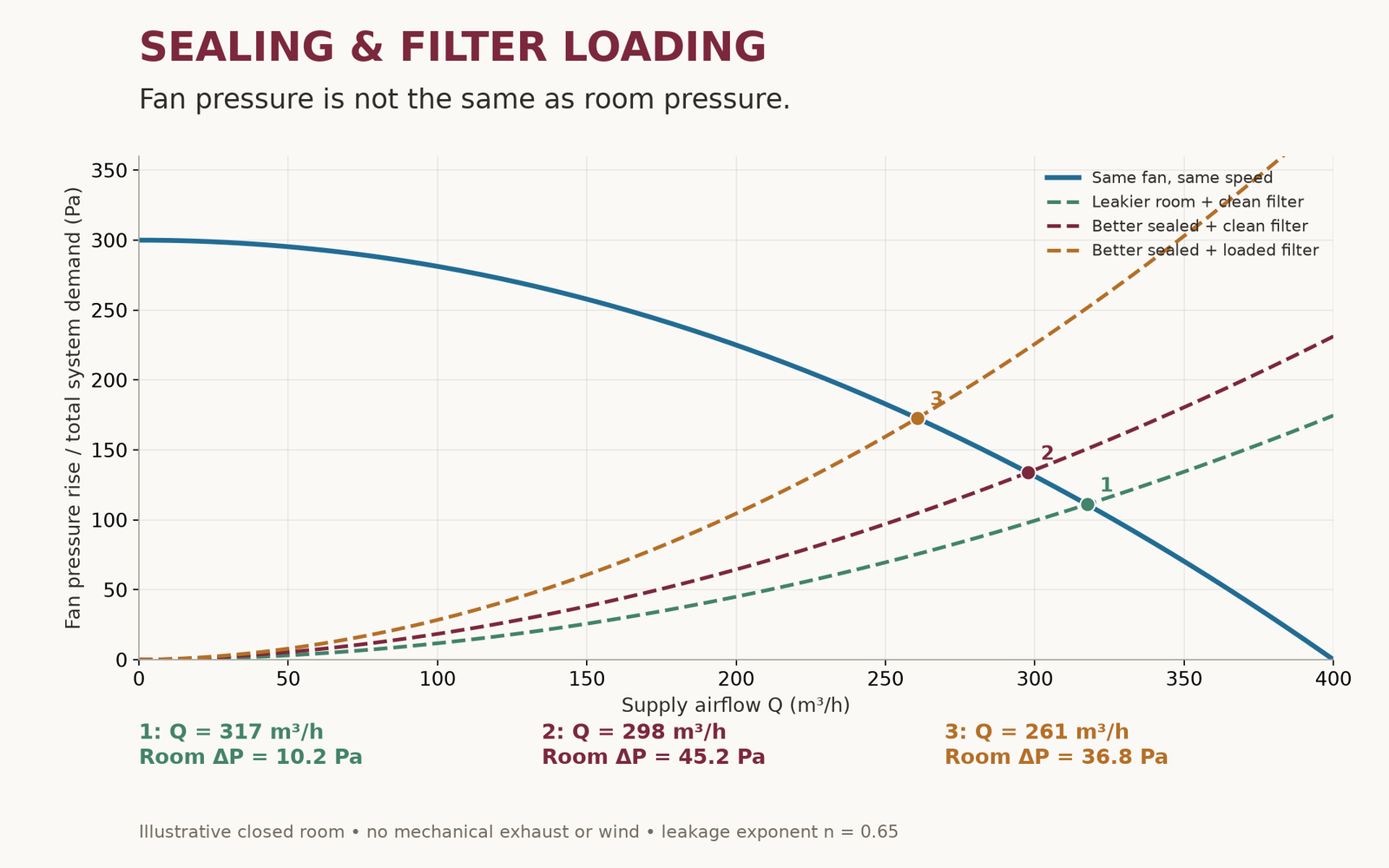
With consistent pressure boundaries, a simplified supply balance is ΔP_fan ≈ ΔP_intake+duct+filter + ΔP_room, with diffuser and installation effects included as appropriate. A 150 Pa fan pressure rise does not imply a +150 Pa room.
The second model holds the fan and speed constant. A leakier room with a clean filter delivers 317 m³/h at +10.2 Pa room pressure; a tighter room gives 298 m³/h at +45.2 Pa; added filter resistance reduces flow to 261 m³/h and room pressure to +36.8 Pa, even as fan pressure rise increases. These are illustrative calculations, not recommended residential pressure setpoints.
Measure room-to-reference pressure separately from fan pressure and filter differential pressure. A higher reading at the fan does not prove better room pressurisation.
Not every system curve is a parabola
A fixed flow path is often approximated by ΔP = KQ² in an appropriate operating range. Use actual clean and replacement-condition filter pressure-drop data rather than forcing every component into a square-law model. Installation conditions matter too. Greenheck system effects
Envelope leakage can be represented by Q_leak = C(ΔP_room)^n, using measured or justified coefficients. The second chart assumes n = 0.65 and adds the resulting room pressure to duct/filter loss. It does not assume a constant room-pressure offset independently of leakage. NIST CONTAM power-law models
Example equations and assumptions
Q: m³/h; ΔP: Pa. A: ΔP = 120[1 − (Q/600)²]; C: ΔP = 360[1 − (Q/500)²]; L: ΔP = 0.0001Q²; H: ΔP = 0.0015Q².
Room model: ΔPfan = 300[1 − (Q/400)²]; ΔPduct+filter = kQ²; Qleak = C(ΔProom)0.65. States 1: C=70, k=0.001; 2: C=25, k=0.001; 3: C=25, k=0.002. C has units (m³/h)/Pa⁰·⁶⁵; k has units Pa/(m³/h)². Supply equals outward leakage, with no exhaust, wind or buoyancy. Boundary velocity-pressure effects are omitted. Only non-negative fan-curve ranges are used.
Centrifugal fans have more than two blade categories
Forward-curved blades curve with rotation. They suit many compact air-handling applications within their pressure rating; absorbed power often rises as flow increases, so unexpectedly low resistance can overload an inadequately sized motor.
Backward-curved or backward-inclined blades face away from rotation. Many designs offer good efficiency and a non-overloading power characteristic: power reaches a maximum rather than rising indefinitely with flow. The selected motor must still cover peak required power and operating limits.
Radial and radial-tip designs serve industrial duties where robustness and the conveyed air matter. They are not automatically the first residential low-noise choice. Airfoil also describes a blade-section form found in high-efficiency designs. Blade geometry, housing and drive are separate classification axes. Greenheck fan-type application guide
Scroll housings and plenum fans are another distinction
A housed/scroll centrifugal fan uses a volute to collect and direct discharge. A plenum/plug fan discharges its wheel into a designed enclosure without its own scroll housing; surrounding clearances and duct connections matter. Mixed-flow fans combine axial and radial flow characteristics, so the available choices extend beyond two families. Greenheck plenum and mixed-flow examples
Why centrifugal is often the starting shortlist for filtered positive pressure
A filtered supply path, ductwork and a fairly tight room require sufficient pressure at the actual duty. A properly selected centrifugal fan is therefore often a suitable starting option, especially with controllable speed and clear performance data.
Define outdoor supply and makeup needs; calculate clean and loaded-filter resistance; find stable operating points; then compare input power, sound and controls. A specialised axial fan that meets the same requirements remains a legitimate option.
Select for changing conditions and commission the installation
Check curves, speed, density, power and permitted operating range, including filter loading and exhaust operation. Avoid stall and unstable regions. Close inlet elbows, restricted intake openings and poor discharge arrangements can reduce actual performance relative to laboratory ratings. Stall guidance; system effects
BLDC/EC identifies the motor-drive technology, not automatic constant airflow or constant room pressure. Appropriate sensing and control are still required. Maintain loaded filters instead of compensating indefinitely beyond fan limits.
For corresponding operating points of the same fan at unchanged density, affinity laws give Q ∝ N, ΔP ∝ N² and shaft power ∝ N³. A 10% speed increase implies roughly 21% greater pressure and 33% greater shaft power under those conditions; it does not guarantee 10% more room airflow in every system. Fan-law conditions
Choose for the room, then verify
Ask: what airflow remains after filtration, where is room pressure measured, and what happens as the filter loads? Engineers should define measurement boundaries and whole-system resistance before selecting a duty point.
The aim is not the largest fan or highest possible pressure. It is reduced uncontrolled dust entry, adequate filtered outdoor air, appropriate exhaust and relief, and energy use suited to demand. Seal, pressurise and filter should become a measurable system.
Every space has its own requirements. Let’s start by understanding yours.
Discuss your project